
Mini Base Board (C) Designed for Raspberry Pi Compute Module 4


€26.17*
Currently out of stock
A confirmed delivery date is not currently available. Please ask us to check current availability.
Product information "Mini Base Board (C) Designed for Raspberry Pi Compute Module 4"
Waveshare CM4-IO-BASE-C (Advanced Ver.) inside, fast and easy to build a mini-computer

* Please refer to the part list for detailed package content

MINI BASE C Advanced Ver

Mini-Computer Kit In addition to the CM4-IO-BASE-C Base Board, it is equipped with Aluminum Alloy case, power supply and fan, etc.
One connection For Display And Touch, Support 70H-1024600-IPS-A Series Display Easier and Faster To Be Integrated into Applications

make it easy to build your own Raspberry Pi CM4 mini PC

| CM4 socket | suitable for all variants of Compute Module 4 |
|---|---|
| Networking | Gigabit Ethernet RJ45 connector |
| Connector | M.2 M KEY, supports communication modules or NVME Solid State Drives |
| Raspberry Pi 40PIN GPIO header | |
| USB | USB 2.0 Type A × 2 |
| Display | LCD port (40pin 0.5mm FPC connector) |
| Camera | MIPI CSI-2 camera port × 2 (15pin 1.0mm FPC connector) |
| Video | HDMI port, supports 4K 30fps output |
| RTC | Real-time clock with battery socket and ability to wake Compute Module 4 |
| Storage | TF card socket for Compute Module 4 Lite (without eMMC) variants |
| Fan header | allows speed adjustment, 5V |
| Power input | 5V |
| Dimensions | 85 × 56mm |
| CM4 Base Board | Interface count and specifications | |||||||||||
|---|---|---|---|---|---|---|---|---|---|---|---|---|
| PoE | Gigabit ETH | 40PIN GPIO | PCIe | USB① | DSI | HDMI | CSI | RTC | Fan Header | Power Input | Features | |
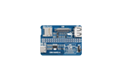 NANO A | √ | 2.0×1 | ×1 | 5V | CM4 sized | |||||||
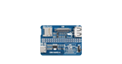 NANO B | ×1 | √ | 2.0×1 | ×1 | ×1 | ×1 | 5V | CM4 sized | ||||
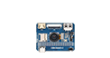 NANO C | √ | 2.0×1 | ×1 | ×1 | ×1 | 5V | Onboard Camera | |||||
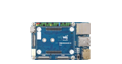 mini Base A | ×1 | √ | M.2 M | 2.0×4 | ×1 | ×2 | ×2 | 5V | 5V | mini size | ||
| mini Base B | ×1 | √ | M.2 M | 2.0×4 | ×1 | ×2 | ×2 | √ | 5V | 5V | mini size | |
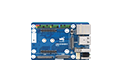 mini Base C | ×1 | √ | M.2 M | 2.0×2 | ×1 | ×2 | √ | 5V | 5V | Dedicated 40PIN LCD Connector | ||
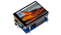 Touch screen | ×1 | M.2 M | 2.0×4 | ×1 | ×1 | 5V | IPS screen | |||||
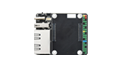 Mini Dual Gigabit | ×2 | √ | 2.0×1 | 5V SH1.0 | 5V | dual ETH | ||||||
 Binocular camera | ×1 | √ | M.2 M | 2.0×4 | ×2 | 5V | dual 8MP cameras | |||||
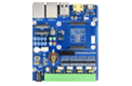 4CH RS485 | ×1 | 2.0×2 | ×1 | ×2 | ×1 | 5V | 7-36V | dual ETH | ||||
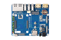 WIFI6 DUAL ETH | ×1 | √ | M.2 E | 2.0×3 | ×1 | ×2 | ×2 | ×1 | 5/12V | 7-36V | WIFI6 dual ETH | |
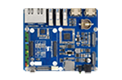 Dual Gigabit ETH | ×2 | √ | 3.0×3 | ×1 | ×2 | ×2 | √ | 5/12V | 7-36V | |||
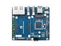 IoT Dual Gigabit ETH | ×2 | √ | 3.0×2 | ×1 | ×2 | ×2 | √ | 5/12V | 5V | 5G/4G support | ||
 IoT Base | √ | ×1 | Gen2×1 | 2.0×2 | ×2 | ×2 | ×2 | √ | 5/12V | 7-36V | 5G/4G supportRS232RS485ADC | |
 PoE Base (B) | √ | ×1 | √ | Gen2×1 | 2.0×4 | ×2 | ×2 | ×2 | √ | 5/12V | 5V | RS232RS485 |
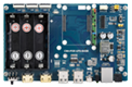 PoE UPS Base | √ | ×1 | √ | M.2 M | 2.0×4 | ×1 | ×2 | ×2 | √ | 5/12V | 7-36V | UPS |
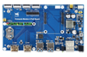 PoE Base | √ | ×1 | √ | 3.0×4 | ×2 | ×2 | ×2 | √ | 5/12V | 7-36V | ||
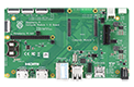 Raspberry Pi official | ② | ×1 | √ | Gen2×1 | 2.0×4 | ×2 | ×2 | ×2 | √ | 12V | 12V | |
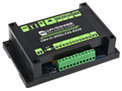 Wireless base | ×1 | M.2 B / Mini-PCIe | 2.0×3 | ×1 | ×1 | √ | 5/12V | 5V or 7-36V | 5G/4G support RS485 CAN rail-mount | |||
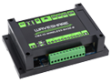 UPS Wireless base | ×1 | M.2 B | 2.0×3 | ×1 | ×1 | √ | 5/12V | 5V or 7-36V | With UPS 5G/4G support RS485 CAN rail-mount | |||
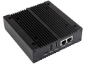 NAS Mini Computer | ×2 | √ | M.2 M×2/ Mini-PCIe | 3.0×2 | ×2 | ×2 | √ | 5V | dual M.2 M KEY slots | |||
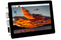 5″ touch screen | ② | ×1 | √ | M.2 M | 2.0×4 | ×1 | ×2 | √ | 5/12V | 5V | ||
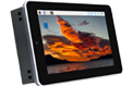 7″ all-in-one | ×1 | M.2 M | 2.0×4 | used | ×1 | used | √ | 5/12V used | 7-36V | touch screen camera speaker | ||
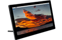 13.3″ all-in-one | ×1 | 2.0×2 | 12V | HD touch screen | ||||||||
 13.3″ Magic Mirror | ×1 | 2.0×2 | 12V | HD screen, Speech Assistant | ||||||||
| Note | ① USB 3.0 is equivalent to USB 3.2 Gen1 ② There's PoE header only on the Raspberry Pi official IO board without PoE circuit, that means additional PoE module is required for the official IO board to enable PoE feature. Unless otherwise specified, the PoE feature here stands for integrating 802.3af-compliant PoE circuit (5V/2.5A). | |||||||||||
The connection cables are in the same direction, neat and convenient


each cut-out is completely aligned with the connector

comes with cooling fan, combined with the airflow vent, better heat dissipation

Suitable for scenarios that require rail mounting, more stable installation

wall mount holes on two sides, handy for mounting

Suitable for binocular Vision Raspberry Pi Projects

Working With An Additional Solid State Drives


- CM4 socket suitable for all variants of Compute Module 4
- Power input/Programming 5V/2.5A power supply, or used for eMMC burning
- LCD Port 40PIN LCD display port, for direct connection to 70H-1024600 series display
- FAN for connecting cooling fan, allows speed adjustment via IO ports
- CAM 2x MIPI CSI camera ports
- HDMI0 connector HDMI0 port, supports 4K 30fps output
- USB 2.0 ports 2x USB 2.0 ports, for connecting sorts of USB devices
- Gigabit Ethernet connector Gigabit Ethernet RJ45 connector, with 10 / 100 / 1000M network support
- M.2 indicator indicating the operating status of M.2 interface
- Raspberry Pi indicators Green LED: PWR, indicating the status of Raspberry Pi power supply Red LED: ACT, indicating the operating status of Raspberry Pi
- Boot switch ON: CM4 would be booted from USB-C interface OFF:CM4 would be booted from eMMC or TF card
- 40PIN GPIO header for connecting sorts of HAT
- TF card slot for connecting a TF card with pre-burnt image (Lite variant ONLY)
- FE1.1S USB HUB chip, support expanding USB port
- M.2 slot supports sorts of NVME Solid State Drives, or communication modules with PCIE M.2 KEY-M interface
- RTC chip allows RTC-related functions like wakeup, shutdown, reboot, and more
- RTC interrupt selection GN-EN: CM4 shutdown(by default) on RTC interruption PI-RUN: CM4 reboot on RTC interruption D4: D4 pin is triggered on RTC interruption
- RTC battery holder supports CR1220 button cell




* Resources for different product may vary, please check the wiki page to confirm the actually provided resources.
Lieferumfang
CM4-IO-BASE-C
- CM4-IO-BASE-C x1
- Solid State Drives mounting screw x1


CM4-IO-BASE-BOX-C
- CM4-IO-BASE-BOX-C x1
- Metal case (top and bottom) x1
- Fan-4010-PWM-5V x1
- Antenna connector rubber plug x1
- Rail-mount buckle x1
- OPTIONS 5V 3A Type-C Power supply x1
- Screws pack x1

Login