
Dual Gigabit Ethernet Mini-Computer Based on Raspberry Pi Compute Module 4 (NOT Included), Metal Case, with Cooling Fan


€84.48*
Currently out of stock
A confirmed delivery date is not currently available. Please ask us to check current availability.
Product information "Dual Gigabit Ethernet Mini-Computer Based on Raspberry Pi Compute Module 4 (NOT Included), Metal Case, with Cooling Fan"
suitable for evaluating the Raspberry Pi CM4 or being integrated into end products
Powerful Ethernet Capability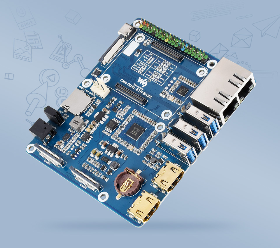
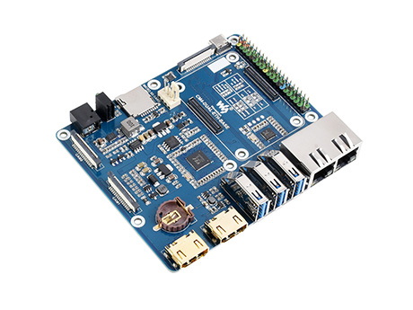
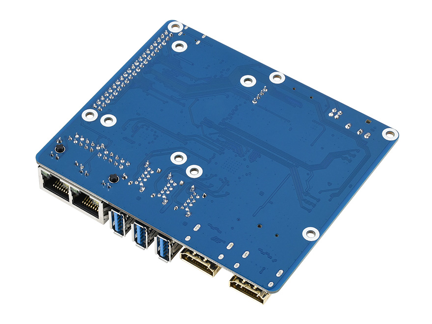
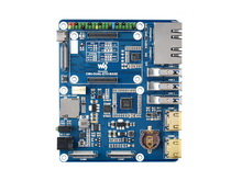
Dual Gigabit Ethernet Base Board
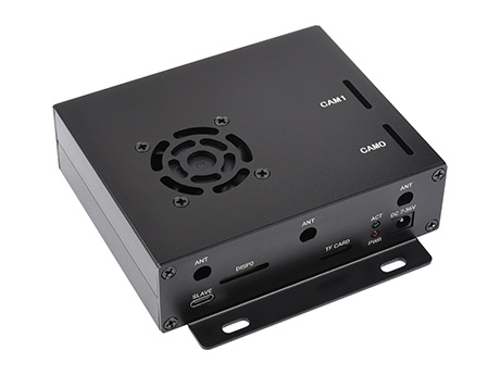
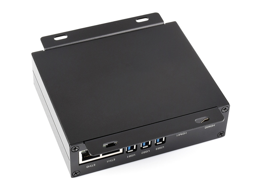
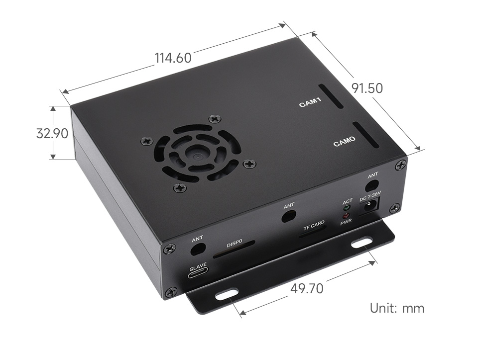
Dual Gigabit Ethernet Mini-Computer Kit In addition to the Dual Gigabit Ethernet Base Board, it is equipped with Aluminum Alloy case, fan and power supply adapter
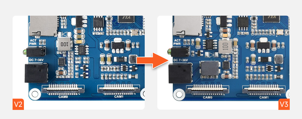
Note: There are two versions of base board: V2 and V3, the components layout are slightly different but the functions are the same
make it easy to build your own Raspberry Pi CM4 mini PC
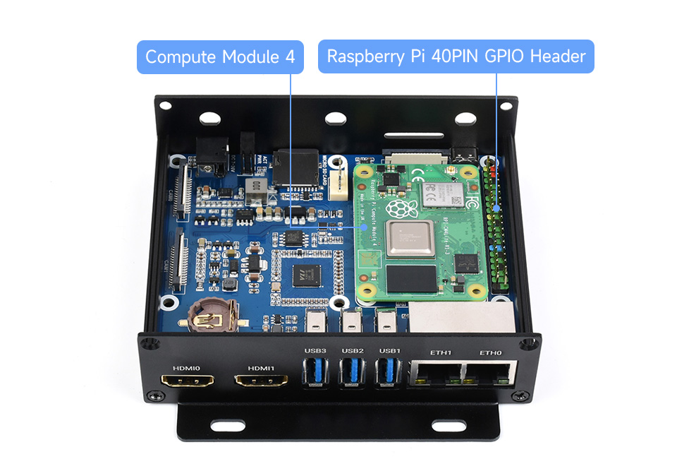
| CM4 socket | suitable for all variants of Compute Module 4 |
|---|---|
| Ethernet | Dual Gigabit Ethernet RJ45 |
| USB | USB 3.2 Gen1 × 3 |
| Pin header | 40PIN GPIO header × 1 |
| DSI display | MIPI DSI display port × 1, 15pin 1.0mm FPC connector |
| CSI camera | MIPI CSI-2 camera port × 2, 15pin 1.0mm FPC connector |
| HDMI | HDMI × 2, supports 4K 30fps output |
| RTC | Real-time clock with battery socket and ability to wake Compute Module 4 |
| TF card slot | TF card socket for Compute Module 4 Lite (without eMMC) variants |
| Fan | 5V/12V, allows speed adjustment and measurement |
| Power input | 7V-36V |
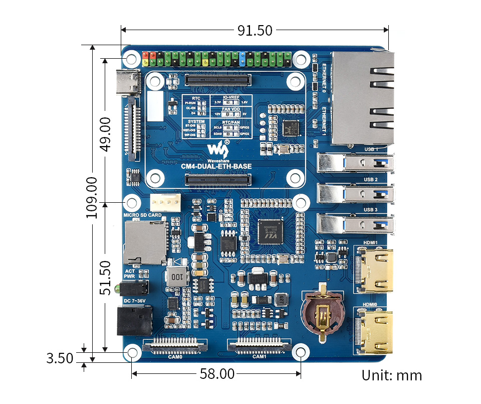
| Dimensions | 109.0 × 91.5mm |
| CM4 Base Board | Interface count and specifications | |||||||||||
|---|---|---|---|---|---|---|---|---|---|---|---|---|
| PoE | Gigabit ETH | 40PIN GPIO | PCIe | USB① | DSI | HDMI | CSI | RTC | Fan Header | Power Input | Features | |
 NANO A NANO A | √ | 2.0×1 | ×1 | 5V | CM4 sized | |||||||
 NANO B NANO B | ×1 | √ | 2.0×1 | ×1 | ×1 | ×1 | 5V | CM4 sized | ||||
 NANO C NANO C | √ | 2.0×1 | ×1 | ×1 | ×1 | 5V | Onboard Camera | |||||
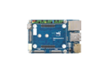 mini Base A mini Base A | ×1 | √ | M.2 M | 2.0×4 | ×1 | ×2 | ×2 | 5V | 5V | mini size | ||
| mini Base B | ×1 | √ | M.2 M | 2.0×4 | ×1 | ×2 | ×2 | √ | 5V | 5V | mini size | |
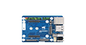 mini Base C mini Base C | ×1 | √ | M.2 M | 2.0×2 | ×1 | ×2 | √ | 5V | 5V | Dedicated 40PIN LCD Connector | ||
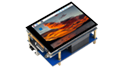 Touch screen Touch screen | ×1 | M.2 M | 2.0×4 | ×1 | ×1 | 5V | IPS screen | |||||
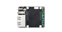 Mini Dual Gigabit Mini Dual Gigabit | ×2 | √ | 2.0×1 | 5V SH1.0 | 5V | dual ETH | ||||||
 Binocular camera Binocular camera | ×1 | √ | M.2 M | 2.0×4 | ×2 | 5V | dual 8MP cameras | |||||
 4CH RS485 4CH RS485 | ×1 | 2.0×2 | ×1 | ×2 | ×1 | 5V | 7-36V | dual ETH | ||||
 WIFI6 DUAL ETH WIFI6 DUAL ETH | ×1 | √ | M.2 E | 2.0×3 | ×1 | ×2 | ×2 | ×1 | 5/12V | 7-36V | WIFI6 dual ETH | |
 Dual Gigabit ETH Dual Gigabit ETH | ×2 | √ | 3.0×3 | ×1 | ×2 | ×2 | √ | 5/12V | 7-36V | |||
 IoT Dual Gigabit ETH IoT Dual Gigabit ETH | ×2 | √ | 3.0×2 | ×1 | ×2 | ×2 | √ | 5/12V | 5V | 5G/4G support | ||
 IoT Base IoT Base | √ | ×1 | Gen2×1 | 2.0×2 | ×2 | ×2 | ×2 | √ | 5/12V | 7-36V | 5G/4G supportRS232RS485ADC | |
 PoE Base (B) PoE Base (B) | √ | ×1 | √ | Gen2×1 | 2.0×4 | ×2 | ×2 | ×2 | √ | 5/12V | 5V | RS232RS485 |
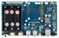 PoE UPS Base PoE UPS Base | √ | ×1 | √ | M.2 M | 2.0×4 | ×1 | ×2 | ×2 | √ | 5/12V | 7-36V | UPS |
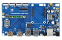 PoE Base PoE Base | √ | ×1 | √ | 3.0×4 | ×2 | ×2 | ×2 | √ | 5/12V | 7-36V | ||
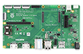 Raspberry Pi official Raspberry Pi official | ② | ×1 | √ | Gen2×1 | 2.0×4 | ×2 | ×2 | ×2 | √ | 12V | 12V | |
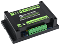 Wireless base Wireless base | ×1 | M.2 B / Mini-PCIe | 2.0×3 | ×1 | ×1 | √ | 5/12V | 5V or 7-36V | 5G/4G support RS485 CAN rail-mount | |||
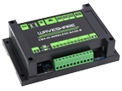 UPS Wireless base UPS Wireless base | ×1 | M.2 B | 2.0×3 | ×1 | ×1 | √ | 5/12V | 5V or 7-36V | With UPS 5G/4G support RS485 CAN rail-mount | |||
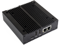 NAS Mini Computer NAS Mini Computer | ×2 | √ | M.2 M×2/ Mini-PCIe | 3.0×2 | ×2 | ×2 | √ | 5V | dual M.2 M KEY slots | |||
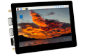 5″ touch screen 5″ touch screen | ② | ×1 | √ | M.2 M | 2.0×4 | ×1 | ×2 | √ | 5/12V | 5V | ||
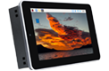 7″ all-in-one 7″ all-in-one | ×1 | M.2 M | 2.0×4 | used | ×1 | used | √ | 5/12V used | 7-36V | touch screen camera speaker | ||
 13.3″ all-in-one 13.3″ all-in-one | ×1 | 2.0×2 | 12V | HD touch screen | ||||||||
 13.3″ Magic Mirror 13.3″ Magic Mirror | ×1 | 2.0×2 | 12V | HD screen, Speech Assistant | ||||||||
| Note | ① USB 3.0 is equivalent to USB 3.2 Gen1 ② There's PoE header only on the Raspberry Pi official IO board without PoE circuit, that means additional PoE module is required for the official IO board to enable PoE feature. Unless otherwise specified, the PoE feature here stands for integrating 802.3af-compliant PoE circuit (5V/2.5A). | |||||||||||
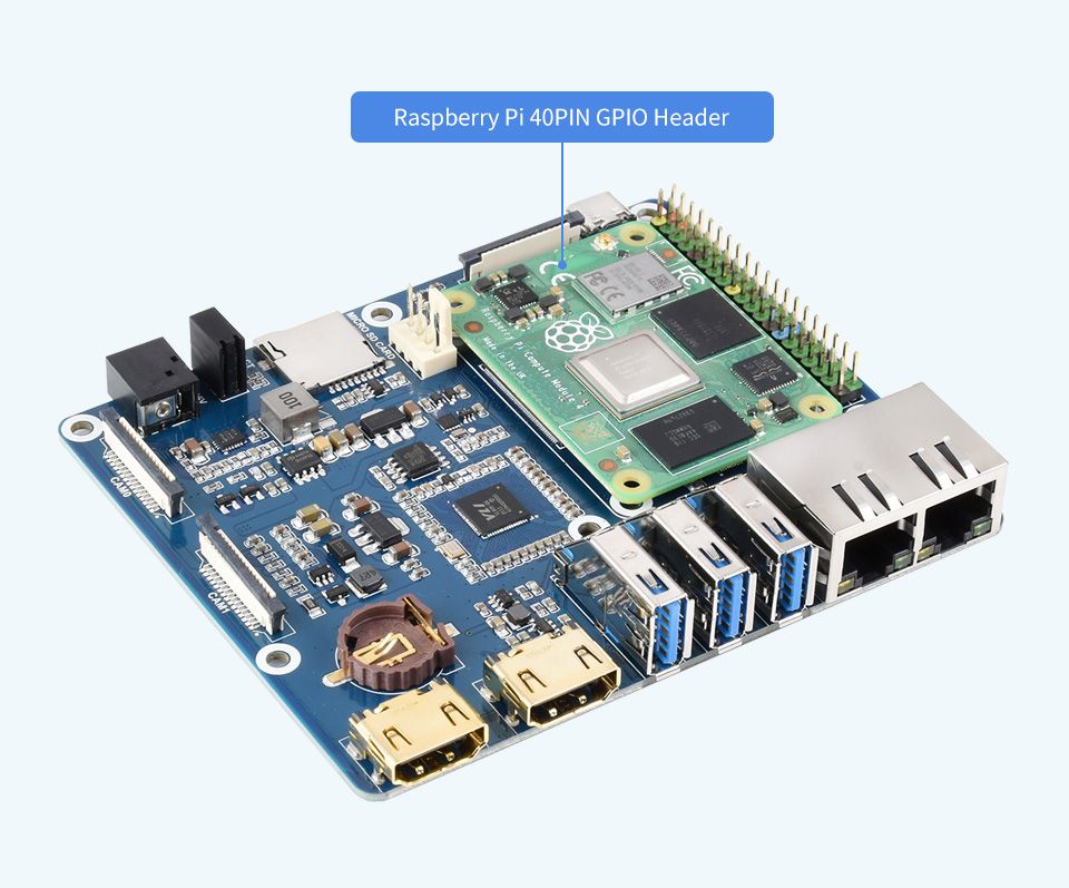
standard CM4 socket and color-coded Raspberry Pi 40PIN GPIO headersuitable for Compute Module 4 Lite/eMMC series module
each cut-out is completely aligned with the connector
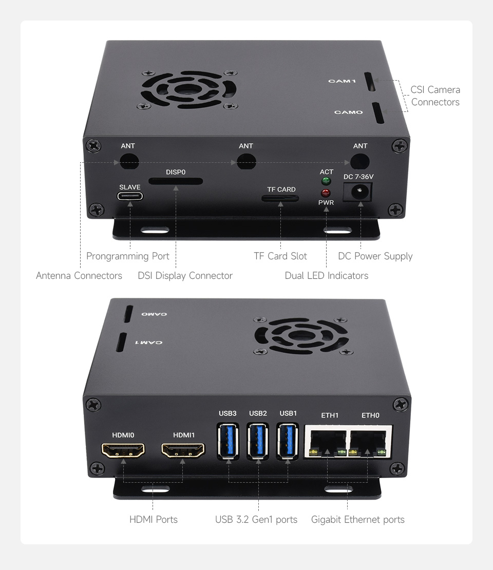
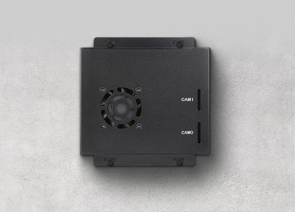
comes with cooling fan, combined with the airflow vent, better heat dissipation
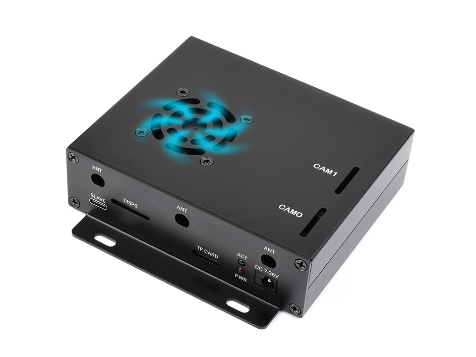
wall mount holes on two sides, handy for mounting
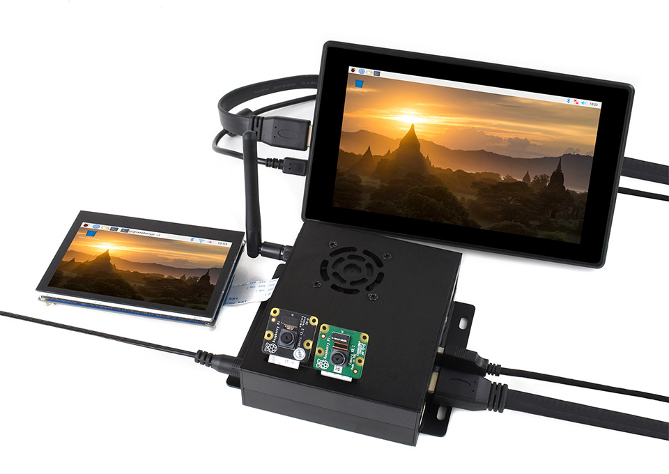
Binocular Vision Raspberry Pi Projects, Or Other Industrial Context
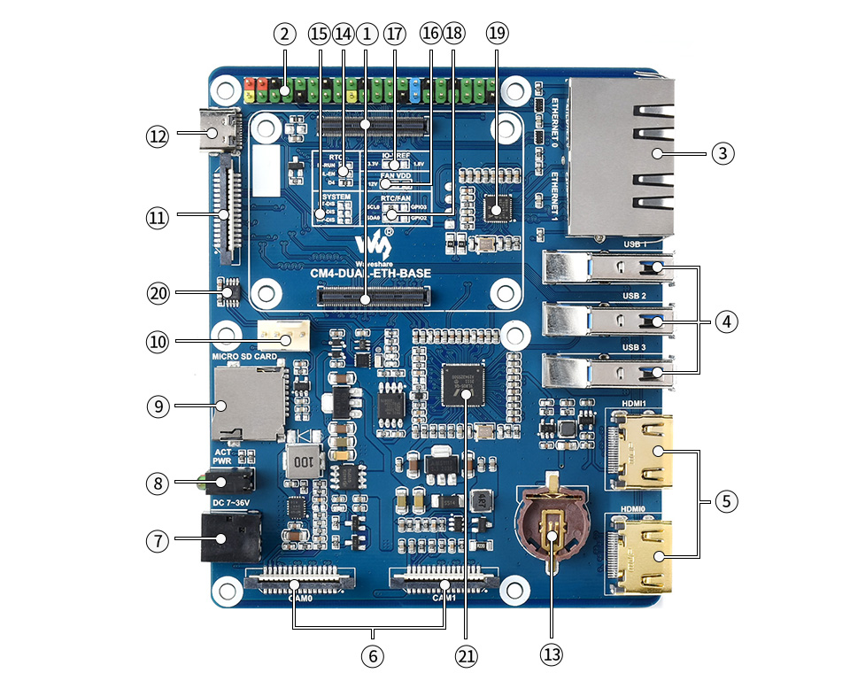
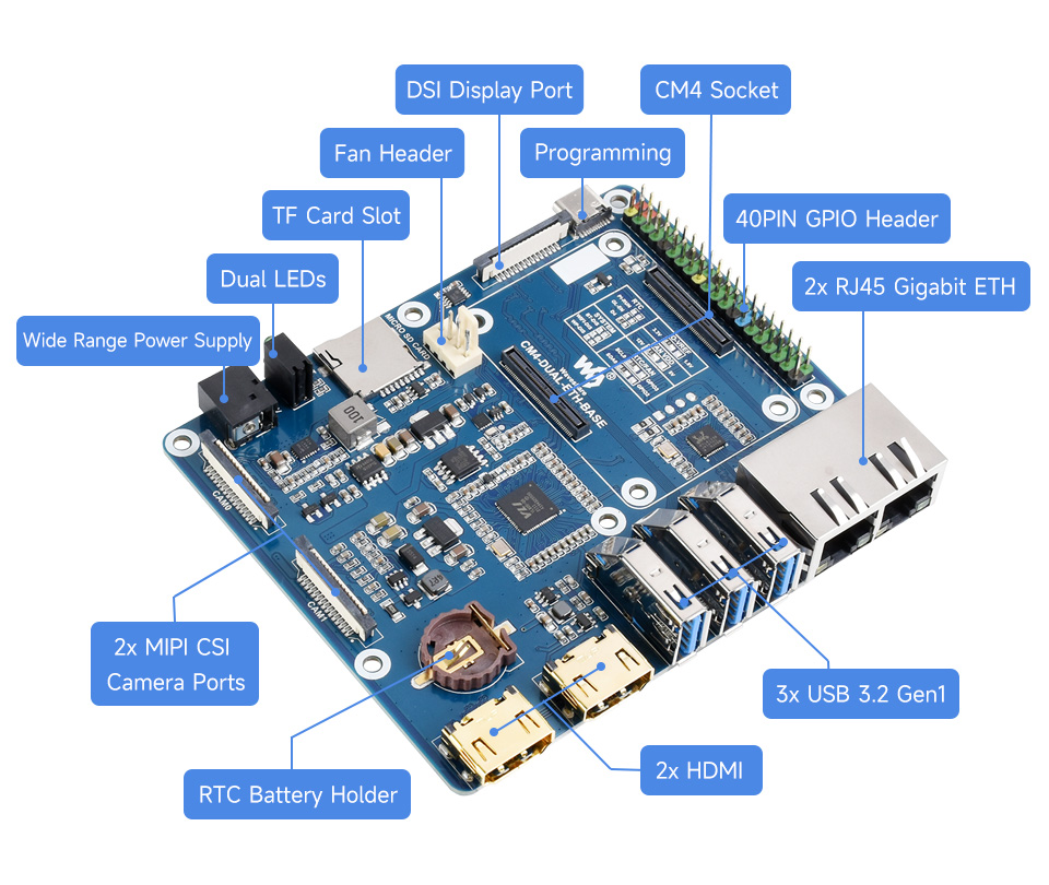
- CM4 socket suitable for all variants of Compute Module 4
- 40PIN GPIO headerfor connecting sorts of HATs
- RJ45 Gigabit Ethernetdual RJ45 Gigabit Ethernet, 10/100/1000M compatibleETHERNET 0: CM4 original ETHETHERNET 1: USB extended ETH
- USB 3.2 ports3x USB 3.2 Gen1, for connecting sorts of USB devices
- HDMI connectors2x HDMI, supports 4K 30fps output
- CAM2x MIPI CSI camera ports
- DC power supply 7~36V DC wide voltage range power input
- Dual LED indicatorsred: Raspberry Pi power indicatorgreen: Raspberry Pi operating status indicator
- TF card slotfor connecting a TF card with pre-burnt image (Lite variant ONLY)
- FAN headerfor connecting cooling fan, allows speed adjustment and measurement
- DISP0MIPI DSI display port
- USB SLAVE portfor burning system image into Compute Module 4 eMMC variants
- RTC battery holdersupports CR1220 button cell
- RTC interruption configuration PI-RUN: CM4 will reboot on RTC interruption GN-EN: CM4 powerdown on RTC interruption D4: D4 pin is triggered on RTC interruption
- IO-VREF selection set the CM4 IO logic level as 3.3V or 1.8V
- FAN power supply selectionselect 5V or 12V power to drive the fan
- System function configurationBT_DIS: Bluetooth disabled, for CM4 with antenna variant ONLYWiFi_DIS: WiFi disabled, for CM4 with antenna variant ONLYWP_DIS: boot mode switch, ONLY be used when NOT booted from eMMC or TF card
- RTC/FAN I2C bus selectionSDA0/SCL0: I2C-10 is shared with CSI/DSIGPIO3/2: I2C-1 is shared with 40PIN header
- RTL8153USB Gigabit Ethernet chip
- EMC2301 fan controller, allows fan speed adjustment and measurement
- VL805 USB 3.0 HUB




* Resources for different product may vary, please check the wiki page to confirm the actually provided resources.
Lieferumfang
CM4-DUAL-ETH-BASE
- CM4-DUAL-ETH-BASE x1
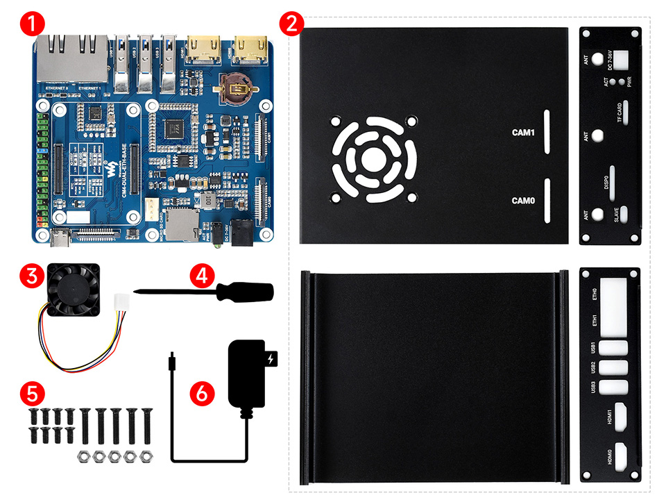
CM4-DUAL-ETH-BOX-A
- CM4-DUAL-ETH-BASE x1
- Metal case (top and bottom) x1
- Fan-4010-PWM-12V x1
- Screwdriver x1
- Screws pack x1
- OPTIONS 12V 2A power adapter x1
Login