
Raspberry Pi Compute Module 4 IO Board, eine Entwicklungsplattform für CM4


45,21 €*
Derzeit nicht auf Lager
Ein verbindlicher Liefertermin liegt derzeit nicht vor. Bitte fragen Sie die aktuelle Verfügbarkeit bei uns an.
Produktinformationen "Raspberry Pi Compute Module 4 IO Board, eine Entwicklungsplattform für CM4"
Kurzbeschreibung: Raspberry Pi Compute Module 4 IO Board, eine Entwicklungsplattform und Referenz-Basisplatine-Design für CM4
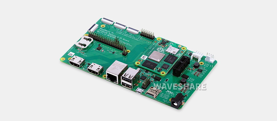
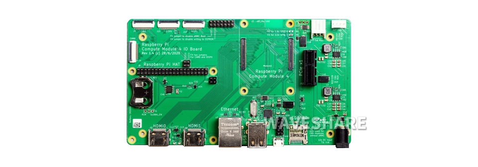
Das Compute Module 4 IO Board ist eine Begleitplatine für das Raspberry Pi Compute Module 4 (separat erhältlich). Es ist sowohl als Entwicklungssystem für das Compute Module 4 als auch als in Endprodukte integrierte Embedded-Platine konzipiert.
Die IO-Platine wurde so entwickelt, dass Sie schnell Systeme mit Standardkomponenten wie HATs und PCIe-Karten erstellen können, die NVMe, SATA, Netzwerk oder USB umfassen können. Die wichtigsten Benutzeranschlüsse befinden sich an einer Seite, um Gehäuse einfach zu gestalten.
Das Compute Module 4 IO Board bietet auch eine hervorragende Möglichkeit, Systeme mit dem Compute Module 4 zu prototypisieren.
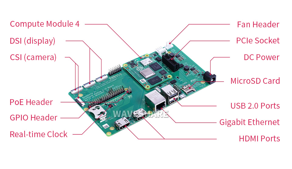
| CM4-Sockel | geeignet für alle Varianten des Compute Module 4 |
|---|---|
| Anschlüsse | Standard-Raspberry-Pi-HAT-Anschlüsse mit PoE-Unterstützung Standard-PCIe-Gen2-x1-Sockel Verschiedene Jumper zum Deaktivieren bestimmter Funktionen, z. B. drahtlose Konnektivität, EEPROM-Schreiben |
| RTC | Echtzeituhr mit Batteriehalterung und der Fähigkeit, das Compute Module 4 zu wecken |
| Video | 2 x MIPI-DSI-Display-FPC-Anschlüsse (22-poliges Kabel mit 0,5 mm Rastermaß) |
| Kamera | 2 x MIPI-CSI-2-Kamera-FPC-Anschlüsse (22-poliges Kabel mit 0,5 mm Rastermaß) |
| USB | 2 x USB-2.0-Anschlüsse Micro-USB-Buchse zum Aktualisieren des Compute Module 4 |
| Ethernet | Gigabit-Ethernet-RJ45 mit PoE-Unterstützung |
| Speichersteckplatz | MicroSD-Kartensteckplatz für Compute-Module-4-Lite-Varianten (ohne eMMC) |
| Lüfter | Standard-Lüfteranschluss |
| Stromeingang | 12V / 5V |
| Abmessungen | 160 × 90mm |
| CM4-Basisplatine | Anzahl und Spezifikationen der Schnittstellen | |||||||||||
|---|---|---|---|---|---|---|---|---|---|---|---|---|
| PoE | Gigabit ETH | 40PIN GPIO | PCIe | USB① | DSI | HDMI | CSI | RTC | Lüfter Anschluss | Strom Eingang | Eigenschaften | |
 NANO A | √ | 2.0×1 | ×1 | 5V | CM4-Größe | |||||||
 NANO B | ×1 | √ | 2.0×1 | ×1 | ×1 | ×1 | 5V | CM4-Größe | ||||
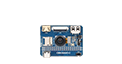 NANO C | √ | 2.0×1 | ×1 | ×1 | ×1 | 5V | Eingebaute Kamera | |||||
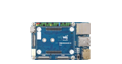 mini Base A | ×1 | √ | M.2 M | 2.0×4 | ×1 | ×2 | ×2 | 5V | 5V | Mini-Größe | ||
| mini Base B | ×1 | √ | M.2 M | 2.0×4 | ×1 | ×2 | ×2 | √ | 5V | 5V | Mini-Größe | |
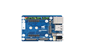 mini Base C | ×1 | √ | M.2 M | 2.0×2 | ×1 | ×2 | √ | 5V | 5V | Spezieller 40PIN-LCD-Anschluss | ||
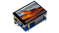 Touchscreen | ×1 | M.2 M | 2.0×4 | ×1 | ×1 | 5V | IPS-Bildschirm | |||||
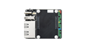 Mini Dual Gigabit | ×2 | √ | 2.0×1 | 5V SH1.0 | 5V | Dual-ETH | ||||||
 Binokulare Kamera | ×1 | √ | M.2 M | 2.0×4 | ×2 | 5V | Dual-8MP-Kameras | |||||
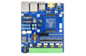 4CH RS485 | ×1 | 2.0×2 | ×1 | ×2 | ×1 | 5V | 7-36V | Dual-ETH | ||||
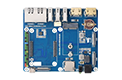 WIFI6 DUAL ETH | ×1 | √ | M.2 E | 2.0×3 | ×1 | ×2 | ×2 | ×1 | 5/12V | 7-36V | WIFI6 Dual-ETH | |
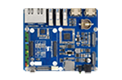 Dual Gigabit ETH | ×2 | √ | 3.0×3 | ×1 | ×2 | ×2 | √ | 5/12V | 7-36V | |||
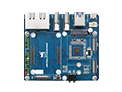 IoT Dual Gigabit ETH | ×2 | √ | 3.0×2 | ×1 | ×2 | ×2 | √ | 5/12V | 5V | 5G/4G-Unterstützung | ||
 IoT Base | √ | ×1 | Gen2×1 | 2.0×2 | ×2 | ×2 | ×2 | √ | 5/12V | 7-36V | 5G/4G-UnterstützungRS232RS485ADC | |
 PoE Base (B) | √ | ×1 | √ | Gen2×1 | 2.0×4 | ×2 | ×2 | ×2 | √ | 5/12V | 5V | RS232RS485 |
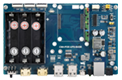 PoE UPS Base | √ | ×1 | √ | M.2 M | 2.0×4 | ×1 | ×2 | ×2 | √ | 5/12V | 7-36V | UPS |
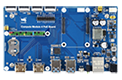 PoE Base | √ | ×1 | √ | 3.0×4 | ×2 | ×2 | ×2 | √ | 5/12V | 7-36V | ||
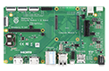 Offiziell von Raspberry Pi | ② | ×1 | √ | Gen2×1 | 2.0×4 | ×2 | ×2 | ×2 | √ | 12V | 12V | |
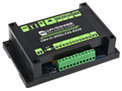 Drahtlose Basis | ×1 | M.2 B / Mini-PCIe | 2.0×3 | ×1 | ×1 | √ | 5/12V | 5V oder 7-36V | 5G/4G-Unterstützung RS485 CAN Hutschiene | |||
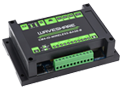 UPS Drahtlose Basis | ×1 | M.2 B | 2.0×3 | ×1 | ×1 | √ | 5/12V | 5V oder 7-36V | Mit UPS 5G/4G-Unterstützung RS485 CAN Hutschiene | |||
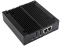 NAS Mini-Computer | ×2 | √ | M.2 M×2/ Mini-PCIe | 3.0×2 | ×2 | ×2 | √ | 5V | Dual-M.2-M-KEY-Steckplätze | |||
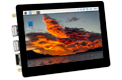 5″ Touchscreen | ② | ×1 | √ | M.2 M | 2.0×4 | ×1 | ×2 | √ | 5/12V | 5V | ||
 7″ All-in-One | ×1 | M.2 M | 2.0×4 | verwendet | ×1 | verwendet | √ | 5/12V verwendet | 7-36V | Touchscreen Kamera Lautsprecher | ||
 13,3″ All-in-One | ×1 | 2.0×2 | 12V | HD-Touchscreen | ||||||||
 13,3″ Magic Mirror | ×1 | 2.0×2 | 12V | HD-Bildschirm, Sprachassistent | ||||||||
| Hinweis | ① USB 3.0 entspricht USB 3.2 Gen1 ② Auf der offiziellen IO-Platine von Raspberry Pi ohne PoE-Schaltung befindet sich nur ein PoE-Anschluss, das bedeutet, dass ein zusätzliches PoE-Modul erforderlich ist, um die PoE-Funktion auf der offiziellen IO-Platine zu aktivieren. Sofern nicht anders angegeben, steht die PoE-Funktion hier für die Integration einer 802.3af-konformen PoE-Schaltung (5V/2,5A). | |||||||||||
Lieferumfang
- Compute Module 4 IO Board x1
Anmelden